Classification of Heat Exchangers
A variety of heat exchangers are used in industry and in their products. Theobjective of this chapter is to describe most of these heat exchangers in some detail using classification schemes. Starting with a definition, heat exchangers are classified according to transfer processes, number of fluids, and degree of surface compactness, construction features, flow arrangements, and heat transfer mechanisms. With a detailed classification in each category, the terminology associated with a variety of these exchangers is introduced and practical applications are outlined. A brief mention is also made of the differences in design procedure for the various types of heat exchangers.
1.1 INTRODUCTIONA heat exchanger is a device that is used to transfer thermal energy (enthalpy)between two or more fluids, between a solid surface and a fluid, or between solidparticulates and a fluid, at different temperatures and in thermal contact. In heat exchangers, there are usually no external heat and work interactions. Typical applications involve heating or cooling of a fluid stream of concern andevaporation or condensation of single- or multicomponent fluid streams. In otherapplications, the objective may be to recover or reject heat, or sterilize, pasteurize, fractionate, distill, concentrate, crystallize, or control a process fluid. In a few heat exchangers, the fluids exchanging heat are in direct contact. In most heat exchangers, heat transfer between fluids takes place through a separating wall. In many heat exchangers, the fluids are separated by a heat transfer surface, and ideally they do not mix or leak. Such exchangers are referred to as direct transfer type, or simply recuperators. In contrast, exchangers in which there is intermittent heat exchange between the hot and cold fluids-via thermal energy storage and release through the exchanger surface or matrix-are referred to as indirect transfer type, or simply regenerators. Such exchangers usually have fluid leakage from onefluid stream to the other, due to pressure differences and matrix rotation/valveswitching. Common examples of heat exchangers are shell-and tube exchangers, automobile radiators, condensers, evaporators, air preheaters, and cooling towers.
If no phase change occurs in any of the fluids in the exchanger, it is sometimesreferred to as a sensible heat exchanger. There could be internal thermal energysources in the exchangers, such as in electric heaters and nuclear fuel elements.Combustion and chemical reaction may take place within the exchanger, such as in boilers, fired heaters, and fluidized-bed exchangers. Heat transfer in the separating wall of a recuperator generally takes place by conduction. However, in a heat pipe heat exchanger, the heat pipe not only acts as a separating wall, but also facilitates the transfer of heat by condensation, evaporation, and conduction of the working fluid inside the heat pipe. In general, if the fluids are immiscible, the separating wall may be eliminated, and the interface between the fluids replaces a heat transfer surface, as in a direct-contact heat exchanger.A heat exchanger consists of heat transfer elements such as a core or matrixcontaining the heat transfer surface, and fluid distribution elements such asheaders, manifolds, tanks, inlet and outlet nozzles or pipes, or seals. Usually, thereare no moving parts in a heat exchanger; however, there are exceptions, such as a rotary regenerative exchanger (in which the matrix is mechanically driven to rotateat some design speed) or a scraped surface heat exchanger.The heat transfer surface is a surface of the exchanger core that is in direct contact with fluids and through which heat is transferred by conduction. That portion of the surface that is in direct contact with both the hot and cold fluids and transfersheat between them is referred to as the primary or direct surface. To increase theheat transfer area, appendages may be intimately connected to the primary surface to provide an extended, secondary, or indirect surface. These extended surface elements are referred to as fins. Thus, heat is conducted through the fin and convicted (and/or radiated) from the fin (through the surface area) to thesurrounding fluid, or vice versa, depending on whether the fin is being cooled orheated. As a result, the addition of fins to the primary surface reduces the thermalresistance on that side and thereby increases the total heat transfer from the surface for the same temperature difference. Fins may form flow passages for the individual fluids but do not separate the two (or more) fluids of the exchanger.These secondary surfaces or fins may also be introduced primarily for structuralstrength purposes or to provide thorough mixing of a highly viscous liquid. Not only heat exchangers are often used in the process, power, petroleum, transportation, air-conditioning, refrigeration, cryogenic, heat recovery, alternative fuel, and manufacturing industries, they also serve as key components of many industrial products available in the marketplace. These exchangers can be classified in many different ways. We will classify them according to transfer processes, number of fluids, and heat transfer mechanisms. Conventional heat exchangers are further classified according to construction type and flow arrangements. Another arbitrary classification can be made, based on the heat transfer surface area/volume ratio, into compact and noncompact heat exchangers.This classification is made because the type of equipment, fields of applications,and design techniques generally differ. All these classifications are summarized inFig. 1.1 and discussed in the following section. Heat exchangers can also beclassified according to the process function. However, they are not discussed here and the student may refer to any textbook. Additional ways to classify heatexchangers are by fluid type (gas–gas, gas–liquid, liquid–liquid, gas two-phase,liquid two-phase etc.), industry, and so on, but we do not cover such classificationsin this chapter.


CLASSIFICATION OF HEAT EXCHANGERS
The word exchanger really applies to all types of equipment in which heat isexchanged but is often used specially to denote equipment in which heat isexchanged between two process streams. Exchangers in which a process fluid isheated or cooled by a plant service stream are referred to as heaters and coolers. Ifthe process stream is vaporized the exchanger is called a vaporizer if the stream is essentially completely vaporized: called a reboiled if associated with a distillation column: and evaporator if used to concentrate a solution. If the process fluid is condensed the exchanger is called a condenser. The term fired exchanger is used for exchangers heated by combustion gases, such as boiler. In heat exchanger the heat transfer between the fluids takes place through a separating wall. The wall may a solid wall or interface. Heat exchangers are used in :• Oil and petrochemical Industry (upstream and downstream) .• Sugar industry• Power generation industry• Air-cooling and refrigeration industryThese heat exchangers may be classified according to:I. Transfer process1. Direct contact2. Indirect contact(a) Direct transfer type(b) Storage type(c) Fluidized bedII. Surface compactness1. Compact (surface area density ≥ 700 m2/m3)2. non-compact (surface area density < 700 m2/m3)III. Construction1. Tubular(a) Double pipe(b) Shell and tube(c) Spiral tube2. Plate(a) Gasketed(b) Spiral plate(c) Welded plate3. Extended surface(a) Plate fin(b) Tube fin4. Regenerative(a) Rotaryi. Disc-typeii. Drum-type(b) Fixed-matrixIV. Flow arrangement1. Single pass(a) Parallel flow(b) Counter flow(c) Cross flow2. Multipass(a) Extended surface heat exchangeri. Cross counter flowii. Cross parallel flow(b) Shell and tube H.E.i. Parallel counter flow (Shell and fluid mixed, M shellpass, N tube pass)ii. Split flowiii. Divided flow(c) Plate Flow arrangement heat exchanger (N-parallel plate multipass)V. Number of fluids1. Two-fluids2. Three-fluids3. N-fluids (N > 3)VI. Transfer mechanisms1. Single phase convection on both sides2. Single phase convection on one side, two-phase convection on the otherside3. Two-phase convection on both sides4. Combined convection and radiative heat transferVII. Classification based on service:Basically, a service may be single phase (such as the cooling or heating of aliquid or gas) or two-phase (such as condensing or vaporizing). Since thereare two sides to a shell and tube heat exchanger, this can lead to severalcombinations of services.Broadly, services can be classified as follows: single-phase (both shell sideand tube side); condensing (one side condensing and the other single-phase); vaporizing (one side vaporizing and the other side single-phase);and condensing/vaporizing (one side condensing and the other sidevaporizing).The following nomenclature is usually used: Heat exchanger: both sides single phase and process streams (that is, not autility). Cooler: one stream is a process fluid and the other cooling water or air.Dirty water can be used as the cooling medium. The top of the cooler isopen to the atmosphere for access to tubes. These can be cleaned withoutshutting down the cooler by removing the distributors one at a time and scrubbing the tubes. Heater: one stream is a process fluid and the other a hot utility, such as steam or hot oil. Condenser: one stream is a condensing vapor and the other cooling water orair. Chiller: one stream is a process fluid being condensed at sub-atmospherictemperatures and the other a boiling refrigerant or process stream. By cooling the falling film to its freezing point, these exchangers convert a variety of chemicals to the solid phase. The most common application is the production of sized ice and paradichlorobenzene. Selective freezing is used for isolating isomers. By melting the solid material and refreezing in several stages, a higher degree of purity of product can be obtained. Reboiler: one stream is a bottom stream from a distillation column and the other a hot utility (steam or hot oil) or a process stream. Evaporators: These are used extensively for the concentration of ammonium nitrate, urea, and other chemicals sensitive to heat when minimum contact time is desirable. Air is sometimes introduced in the tubes to lower the partial pressure of liquids whose boiling points are high. These evaporatorsare built for pressure or vacuum and with top or bottom vapor removal. Absorbers: These have a two-phase flow system. The absorbing medium isput in film flow during its fall downward on the tubes as it is cooled by a cooling medium outside the tubes. The film absorbs the gas which is introduced into the tubes. This operation can be concurrent or countercurrent. Falling-Film Exchangers: Falling-film shell-and-tube heat exchangers havebeen developed for a wide variety of services. The fluid enters at the top ofthe vertical tubes. Distributors or slotted tubes put the liquid in film flow in the inside surface of the tubes, and the film adheres to the tube surface while falling to the bottom of the tubes. The film can be cooled, heated, evaporated, or frozen by means of the proper heat-transfer medium outside the tubes. Tube distributors have been developed for a wide range ofapplications. Fixed tube sheets, with or without expansion joints, and outside-packed-head designs are used. Principal advantages are high rate of heat transfer, no internal pressure drop, short time of contact (very important for heat-sensitive materials), easy accessibility to tubes forcleaning, and, in some cases, prevention of leakage from one side to another. These falling-film exchangers are used in various services as described in the following paragraphs.Among these classifications the classification by construction is the most widely used one
CLASSIFICATION BY CONSTRUCTION
The principal types of heat exchanger are listed again as1. Tubular exchanger2. Plate exchanger3. Extended surface4. Regenerative3.1 Tubular heat exchangerTubular heat exchangers are generally built of circular tubes. Tubular heatexchanger is further classified into:1. Double pipe heat exchanger2. Spiral tube heat exchanger3. Shell and tube heat exchanger1.3.1.1 Double pipe heat exchangerThis is usually consists of concentric pipes as shown in Fig. 1.2. One fluid flowflows in the inner pipe and the other fluid flows in the annulus between pipes. Thetwo fluids may flow concurrent (parallel) or in counter current flow configuration;hence the heat exchanger are classified as: Counter current double pipe heat exchanger Concurrent (parallel) double pipe heat exchanger

Double pipe heat exchanger is perhaps the simplest of all heat exchanger types.
The advantages of this type include ease of disassembly, no cleaning problem, and
suitable for high pressure fluid, (the pressure containment in the small diameter
pipe or tubing is a less costly method compared to a large diameter shell). The
double pipe heat exchanger is generally used for the application where the total
heat transfer surface area required is less than or equal to 20 m2 (215 ft2) because
it is expensive on a cost per square meter (foot) basis.
1.3.1.2 Spiral tube heat exchanger
Spiral tube heat exchanger illustrated in Fig. 1.3 consists of one or more spirally
wound coils fitted in a shell (Fig. 1.3). Heat transfer associated with spiral tube is
higher than that for a straight tube. In addition, considerable amount of surface area
can be accommodated in a given space by spiraling. The advantages of spiral type heat exchanger are:
a. Self Cleaning: The scrubbing effect in each single channel removes deposits as
they form. Suspended solids tend to settle during low flow rates or shutdown,
which often leads to clogging in multiple-channel designs. This cleaning feature
is particularly advantageous to combat clogging in a horizontally mounted unit.
Particles tend to accumulate in the bottom of each channel curvature. This
resulting restriction of the channel cross-section increases the fluid velocity at
the exact area affected and any deposits are immediately flushed away.
b. Low Fouling: The high turbulence created by the continuously curving channels
minimizes fouling and scaling tendencies. This means that the spiral design
improves heat transfer surface than a shell-and-tube heat exchanger. Moreover,
this also means that the design requires less frequent cleaning.
c. Easy Access: Removing the covers on both ends of the spiral heat exchanger
makes the entire length of each of the channels easily accessible for inspection
or mechanical cleaning, if necessary. Should scaling or fouling occur, cleaning-
in-place is effective without even opening the unit.
d. Small Space Requirements: The circular arrangement of the two channels makes
an extremely compact heat exchanger. For example, 100 m² (1080 ft²) of heat
transfer surface fits into a heat exchanger only one metre in diameter and 1.5
metres long. The only service space required is that for the removal of the
covers.

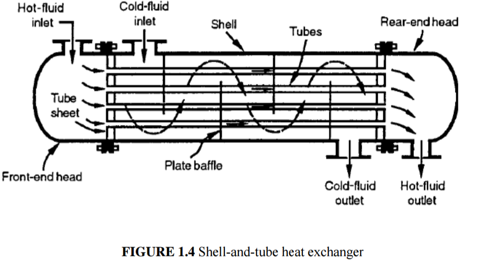
1.3.1.3 Shell-and-tube heat exchanger
Shell and tube heat exchangers in their various modifications are probably the most
widespread and commonly used basis heat exchanger configuration in the process
industries. The reasons for this general acceptance are several. The shell and tube
heat exchanger provides a comparatively large ratio of heat transfer area to volume
and weight. It provides this surface in a form which is relatively easy to construct
in a wide range of sizes and which is mechanically rugged enough to withstand
normal shop fabrication stresses, shipping and field erection stresses, and normal
operating conditions. The shell and tube can reasonably easily be cleaned, and
those components most subject to failure-gasket and tubes- can be easily replaced.
Shell and tube heat exchanger is built of round tubes mounted in a cylindrical shell
with the tube axis parallel to that of the shell. One fluid flows inside the tube, the
other flows across and along the tubes. The major components of the shell and
tube heat exchanger are tube bundle, shell, front end head, rear end head, baffles
and tube sheets (Fig.1.4).

The shell-and-tube heat exchanger is further divided into three categories as
1. Fixed tubesheet.
2. U tube
3. Floating head
1.3.1.3.1 Fixed tubesheet shell-and-tube heat exchanger
A fixed-tubesheet heat exchanger (Fig. 1.5) has straight tubes that are secured at
both ends to tubesheets welded to the shell. The construction may have removable
channel covers, bonnet-type channel covers, or integral tubesheets. The principal
advantage of the fixed tubesheet construction is its low cost because of its simple
construction. In fact, the fixed tubesheet is the least expensive construction type, as
long as no expansion joint is required.
Other advantages are that the tubes can be cleaned mechanically after removal
of the channel cover or bonnet, and that leakage of the shell side fluid is
minimized since there are no flanged joints. A disadvantage of this design is that
since the bundle is fixed to the shell and cannot be removed, the outsides of the
tubes cannot be cleaned mechanically. Thus, its application is limited to clean
services on the shell side. However, if a satisfactory chemical cleaning program
can be employed, fixed-tubesheet construction may be selected for fouling services
on the shell side. In the event of a large differential temperature between the
tubes and the shell, the tubesheets will be unable to absorb the differential
stress, thereby making it necessary to incorporate an expansion joint. This takes
away the advantage of low cost to a significant extent.

1.3.1.3.2 U-tube shell-and-tube heat exchanger
As the name implies, the tubes of a U-tube heat exchanger (Fig. 1.6) are bent
in the shape of a U. There is only one tubesheet in a U tube heat exchanger.
However, the lower cost for the single tubesheet is offset by the additional costs
incurred for the bending of the tubes and the somewhat larger shell diameter (due
to the minimum U-bend radius), making the cost of a U-tube heat exchanger
comparable to that of a fixed tubesheet exchanger.
The advantage of a U-tube heat exchanger is that because one end is free, the bundle can expand or contract in response to stress differentials. In addition, the
outsides of the tubes can be cleaned, as the tube bundle can be removed. The
disadvantage of the U-tube construction is that the insides of the tubes cannot be
cleaned effectively, since the U-bends would require flexible- end drill shafts for
cleaning. Thus, U-tube heat exchangers should not be used for services with a dirty
fluid inside tubes.

1.3.1.3.2 Floating head shell-and-tube heat exchanger
The floating-head heat exchanger is the most versatile type of shell and tube heat
exchanger, and also the costliest. In this design, one tubesheet is fixed relative to
the shell, and the other is free to “float” within the shell. The floating head can
move axially, and the shell side is sealed by a packing (26) that is compressed by
means of a packing gland (28). The floating tubesheet skirt (29) diameter is smaller
than that of the shell. It thus can be removed to the left, passing through the shell,
when the unit is disassembled. The slip-on backing flange (30) is a loose flange that can be removed to the right after removal of the split shear ring (31). This
permits free expansion of the tube bundle, as well as cleaning of both the insides
and outsides of the tubes. Thus, floating-head SHTEs can be used for services
where both the shellside and the tubeside fluids are dirty-making as shown in Fig.
1.7. This type is the standard construction type used in dirty services, such as in
petroleum refineries.

 |
In the design without packing service construction (Fig. 1.8), the entire tube
bundle, including the floating-head assembly, can be removed from the stationary
end, since the shell diameter is larger than the floating-head flange. The floating
head cover is bolted directly to the floating tubesheet so that a split backing ring is
not required. The advantage of this construction is that the tube bundle may be
removed from the shell without removing either the shell or the floating head cover, thus reducing maintenance time. This design is particularly suited to kettle
reboilers having a dirty heating medium where U- tubes cannot be employed. Due
to the enlarged shell, this construction has the highest cost of all exchanger types.

1.3.2 Plate heat exchanger
These exchangers are generally built of thin plates. The plate are either smooth or
have some form of corrugations and they are either flat or wound in exchanger.
Generally, theses exchanger cannot accommodate high pressure/temperature
differential relative the tubular exchanger. This type of exchanger is further
classified as:
1. Gasketed plate
2. Welded-and-brazed plate
3. Spiral plate
4. Lamela
5. Platecoil
1.3.2.1 Gasketed plate heat exchanger
The plate-and-frame or gasketed plate heat exchanger (PHE) (see Fig. 1.9) consists
of a number of thin rectangular metal plates sealed around the edges by gaskets
and held together in a frame as shown in Fig. 1.16. The frame usually has a fixed
end cover (headpiece) fitted with connecting ports and a movable end cover
(pressure plate, follower, or tailpiece). In the frame, the plates are suspended from
an upper carrying bar and guided by a bottom carrying bar to ensure proper
alignment. For this purpose, each plate is notched at the centre of its top and
bottom edges. The plate pack with fixed and movable end covers is clamped
together by long bolts, thus compressing the gaskets and forming a seal. The
carrying bars are longer than the compressed stack, so that when the movable end
cover is removed, plates may be slid along the support bars for inspection and
cleaning.


Close temperature approaches and tight temperature control possible with PHE’s
and the ability to sanitize the entire heat transfer surface easily were a major
benefit in the food and pharmaceutical industry. Limitation of this type of heat
exchanger includes low pressure <30 bar (plate deformation), and Working
temperature of < (500 F) [250 o C] (maximum gasket temperature).
1.3.2.2 Welded- and-brazed- plate heat exchanger (W. PHE and BHE)
One of the limitations of the gasketed plate heat exchanger is the presence of
gaskets, which restricts their use to compatible fluids (non-corrosive fluids) and
which limits operating temperatures and pressures. To overcome this limitation, a
number of welded plate heat exchanger designs have surfaced with welded pairs of
plates on one or both fluid sides. To reduce the effective welding cost, the plate
size for this exchanger is usually larger than that of the gasketed PHE. The
disadvantage of such a design is the loss of disassembling flexibility on the fluid
sides where the welding is done. Essentially, laser welding is done around the
complete circumference, where the gasket is normally placed. Welding on both
sides then results in higher limits on operating temperatures and pressures [350o
C
(6608 F) and 4.0MPa (580 psig)] and allows the use of corrosive fluids compatible
with the plate material. Welded PHEs can accommodate multiple passes and more
than two fluid streams. A Plate heat exchanger can accommodate four fluid
streams. Figure 1.10 shows a pack of plates for a conventional plate-and-frame
exchanger, but welded on one fluid side. Materials used for welded PHEs are
stainless steel, Hastelloy, nickel-based alloys, and copper and titanium.
Typical applications include district heating where the low cost and minimal
maintenance have made this type of heat exchanger especially attractive. Most
methods of welded-plate manufacturing do not allow for inspection of the heat-
transfer surface, mechanical cleaning of that surface, and have limited ability to
repair or plug off damage channels. Consider these limitations when the fluid is
heavily fouling, has solids, or in general the repair or plugging ability for severe
services.

1.3.2.3 Spiral plate heat exchanger
A spiral plate heat exchanger consists of two relatively long strips of sheet metal,
normally provided with welded studs for plate spacing, wrapped helically around a
split mandrel to form a pair of spiral channels for two fluids, as shown in Fig. 1.11.
Alternate passage edges are closed. Thus, each fluid has a long single passage
arranged in a compact package. To complete the exchanger, covers are fitted at
each end. Any metal that can be cold-formed and welded can be used for this
exchanger. Common metals used are carbon steel and stainless steel. Other
Metals include titanium, Hastelloy, Incoloy, and high-nickel alloys. The basic
spiral element is sealed either by welding at each side of the channel or by
providing a gasket (non–asbestos based) at each end cover to obtain the following
alternative arrangements of the two fluids: (1) both fluids in spiral counterflow; (2)
one fluid in spiral flow, the other in crossflow across the spiral; or (3) one fluid in
spiral flow, the other in a combination of crossflow and spiral flow. The entire
assembly is housed in a cylindrical shell enclosed by two (or only one or no)
circular end covers (depending on the flow arrangements above), either flat or
conical. Carbon steel and stainless steel are common materials. Other materials
used include titanium, Hastelloy, and Incoloy.

A spiral plate exchanger has a relatively large diameter because of the spiral turns.
The largest exchanger has a maximum surface area of about 500 m2
(5400 ft2
) for a
maximum shell diameter of 1.8 m (72 in.). The typical passage height is 5 to 25
mm (0.20 to 1.00 in.) and the sheet metal thickness range is 1.8 to 4mm (0.07 to
0.16 in.).
The heat transfer coefficients are not as high as in a plate exchanger if the plates
are not corrugated. However, the heat transfer coefficient is higher than that for a
shell-and-tube exchanger because of the curved rectangular passages. Hence, the
surface area requirement is about 20% lower than that for a shell-and-tube unit for
the same heat duty. The counterflow spiral unit is used for liquid–liquid,
condensing, or gas cooling applications. When there is a pressure drop constraint
on one side, such as with gas flows or with high liquid flows, crossflow (straight
flow) is used on that side. For condensation or vaporization applications, the unit is
mounted vertically. Horizontal units are used when high concentrations of solids
exist in the fluid. The advantages of this exchanger are as follows: It can handle
viscous, fouling liquids and slurries more readily because of a single passage. If the
passage starts fouling, the localized velocity in the passage increases. The fouling
rate then decreases with increased fluid velocity. The fouling rate is very low
compared to that of a shell-and-tube unit. It is more amenable to chemical, flush,
and reversing fluid cleaning techniques because of the single passage. Mechanical cleaning is also possible with removal of the end covers. Thus, maintenance is less
than with a shell-and-tube unit. No insulation is used outside the exchanger
because of the cold fluid flowing in the outermost passage, resulting in negligible
heat loss, if any, due to its inlet temperature closer to surrounding temperature. The
internal void volume is lower (less than 60%) than in a shell-and-tube exchanger,
and thus it is a relatively compact unit. By adjusting different channel heights,
considerable differences in volumetric flow rates of two streams can be
accommodated.
The disadvantages of this exchanger are as follows: As noted above, the maximum
size is limited. The maximum operating pressure ranges from 0.6 to 2.5MPa gauge
(90 to 370 psig) for large units. The maximum operating temperature is limited to
5008C (9308F) with compressed asbestos gaskets, but most are designed to operate
at 2008C (3928F). Field repair is difficult due to construction features. This
exchanger is well suited as a condenser or reboiler. It is used in the cellulose
industry for cleaning relief vapors in sulfate and sulfite mills, and is also used as a
thermosiphon or kettle reboiler. It is preferred especially for applications having
very viscous liquids, dense slurries, digested sewage sludge, and contaminated
industrial effluents.
A spiral version free of welded studs for plate spacing on one or both fluid sides
but with reduced width is used for sludge and other heavily fouling fluids. It is also
used in the treatment of bauxite suspensions and mash liquors in the alcohol
industry.
1.3.2.4 Lamella heat exchanger
A lamella heat exchanger consists of an outer tubular shell surrounding an inside
bundle of heat transfer elements. These elements, referred to as lamellas, are flat
tubes (pairs of thin dimpled plates, edge welded, resulting in high-aspect-ratio
rectangular channels), shown in Fig. 1.12a. The inside opening of the lamella
ranges from 3 to 10 mm (0.1 to 0.4 in.) and the wall thickness from 1.5 to 2mm
(0.06 to 0.08 in.). Lamellas are stacked close to each other to form narrow channels
on the shell side. Lamellas are inserted in the end fittings with gaskets to prevent
the leakage from shell to tube side, or vice versa. In a small exchanger, lamellas
are of increasing width from either end to the centre of the shell to fully utilize the available space, as shown in Fig. 1.123a. However, in a larger exchanger, lamellas
consist of two (see Fig. 1.123b) or more flat tubes to contain operating pressures.
There are no baffles. One end of the tube bundle is fixed and the other is floating,
to allow for thermal expansion. Thus, this exchanger is a modified floating-head
shell-and-tube exchanger. One fluid (tube fluid) flows inside the lamellas and the
other fluid (shell fluid) flows longitudinally in the spaces between them, with no
baffles on the shell side. The exchanger thus has a single pass, and the flow
arrangement is generally counterflow. The flat tube walls have dimples where
neighbouring tubes are spot-welded. High-heat-transfer coefficients are usually
obtained because of small hydraulic diameters and no leakage or bypass streams as
encountered in a conventional shell-and-tube exchanger. Also, possible point
dimples increase the heat transfer coefficient and pressure drop in the same way as
do corrugated plate channels. This exchanger is used for heat recovery in the pulp
and paper industry, chemical process industry, and for other industrial applications,
in competition with the shell-and-tube exchanger. cross section of a lamella heat exchanger; (c) lamellas.")
 cross section of a lamella heat exchanger; (c) lamellas.")
1.3.3 Extended surface
The tubular and plate-type exchangers described previously are all prime surface
heat exchangers, except for a shell-and-tube exchanger with low finned tubing.
Their heat exchanger effectiveness is usually 60% or below, and the heat transfer
surface area density is usually less than 700 m2
/m3
(213 ft2
/ft3
). In some
applications, much higher (up to about 98%) exchanger effectiveness is essential,
and the box volume and mass are limited so that a much more compact surface is
mandated. Also, in a heat exchanger with gases or some liquids, the heat transfer
coefficient is quite low on one or both fluid sides. This results in a large heat
transfer surface area requirement. One of the most common methods to increase
the surface area and exchanger compactness is to add the extended surface (fins)
and use fins with the fin density (fin frequency, fins/m or fins/in.) as high as
possible on one or both fluid sides, depending on the design requirement. Addition
of fins can increase the surface area by 5 to 12 times the primary surface area in
general, depending on the design. The resulting exchanger is referred to as an
extended surface exchanger. The heat transfer coefficient on extended surfaces
may be higher or lower than that on un-finned surfaces. For example, interrupted
(strip, louver, etc.) fins provide both an increased area and increased heat transfer
coefficient, while internal fins in a tube increase the tube-side surface area but may
result in a slight reduction in the heat transfer coefficient, depending on the fin
spacing. Generally, increasing the fin density reduces the heat transfer coefficient
associated with fins. Flow interruptions (as in offset strip fins, louvered fins, etc.)
may increase the heat transfer coefficient two to four times that for the
corresponding plain (uncut) fin surface. Plate-fin and tube-fin geometries are the
two most common types of extended surface heat exchangers.
1.3.3.1 Plate-fin heat exchanger
This type of exchanger has corrugated fins (most commonly having triangular and
rectangular cross sections) or spacers sandwiched between parallel plates (referred
to as plates or parting sheets), as shown in Fig. 1.13.

Sometimes fins are incorporated in a flat tube with rounded corners (referred to as
a formed tube), thus eliminating the need for side bars. Fins are die- or roll- formed
and are attached to the plates by brazing, soldering, adhesive bonding, welding,
mechanical fit, or extrusion. Fins may be used on both sides in gas-to-gas heat
exchangers. In gas-to-liquid applications, fins are generally used only on the gas
side; if employed on the liquid side, they are used primarily for structural strength
and flow-mixing purposes. Fins are also sometimes used for pressure containment
and rigidity. In Europe, a plate-fin exchanger is also referred to as a matrix heat
exchanger.
Plate fins are categorized as (1) plain (i.e., uncut) and straight fins, such as plain
triangular and rectangular fins, (2) plain but wavy fins (wavy in the main fluid flow
direction), and (3) interrupted fins, such as offset strip, louver, perforated, and pin
fins. Examples of commonly used fins are shown in Fig. 1.14. plain triangular fin; (b) plain rectangular fin; (c) wavy fin; (d) offset strip fin; (e) multilouver fin; (f) perforated fin.")

Plate-fin exchangers are generally designed for moderate operating pressures [less
than about 700 kPa gauge (100 psig)], although plate-fin exchangers are available
commercially for operating pressures up to about 8300 kPa gauge (1200 psig).
Recently, a condenser for an automotive air-conditioning system using carbon
dioxide as the working fluid has been developed for operating pressures of 14 MPa
(2100 psia). A recently developed titanium plate-fin exchanger (manufactured by
superelastic deformation and diffusion bonding can take 35 MPa
(5000 psig) and higher pressures. The temperature limitation for plate-fin
exchangers depends on the method of bonding and the materials employed. Such
exchangers have been made from metals for temperatures up to about 8408 o
C
(1550 F) and made from ceramic materials for temperatures up to about 1150 o
C
(21008 F) with a peak temperature of 1370 o
C (2500F). For ventilation
applications (i.e., preheating or precooling of incoming air to a building/room), the
plate-fin exchanger is made using Japanese treated (hygroscopic) paper and has the
operating temperature limit of 50 o
C (122 F). Thus, plates and fins are made from a variety of materials, metals, ceramics, and papers. Plate fin exchangers have been
built with a surface area density of up to 5900 m2
/m3
(1800 ft2
/ ft3
). There is total
freedom in selecting the fin surface area on each fluid side, as required by the
design, by varying the fin height and fin density. Although typical fin densities are
120 to 700 fins/m (3 to 18 fins/in.), applications exist for as many as 2100 fins/m
(53 fins/in.). Common fin thickness ranges between 0.05 and 0.25 mm (0.002 to
0.01 in.). Fin heights may range from 2 to 25mm(0.08 to 1.0 in.). A plate-fin
exchanger with 600 fins/m (15.2 fins/in.) provides about 1300 m2
(400 ft2
/ft3
) of
heat transfer surface area per cubic meter of volume occupied by the fins. Plate-fin
exchangers are manufactured in virtually all shapes and sizes and are made from a
variety of materials. A cryogenic plate-fin exchanger has about 10% of the volume
of an equivalent shell-and-tube exchanger.
Plate-fin exchangers have been produced since the 1910s in the auto industry
(copper fin–brass tubes), since the 1940s in the aerospace industry (using
aluminium), and in gas liquefaction applications since the 1950s using aluminium
because of the better mechanical characteristics of aluminium at low temperatures.
They are now used widely in electric power plants (gas turbine, steam, nuclear,
fuel cell, etc.), propulsive power plants (automobile, truck, airplane, etc.), systems
with thermodynamic cycles (heat pump, refrigeration, etc.), and in electronic,
cryogenic, gas-liquefaction, air-conditioning, and waste heat recovery systems.
1.3.3.1 Tube-fin heat exchanger
These exchangers may be classified as conventional and specialized tube-fin
exchangers. In a conventional tube-fin exchanger, heat transfer between the two
fluids takes place by conduction through the tube wall. However, in a heat pipe
exchanger (a specialized type of tube-fin exchanger), tubes with both ends closed
act as a separating wall, and heat transfer between the two fluids takes place
through this ‘‘separating wall’’ (heat pipe) by conduction, and evaporation and
condensation of the heat pipe fluid. Let us first describe conventional tube-fin
exchangers and then heat pipe exchangers.
Conventional tube-fin exchangers. In a gas-to-liquid exchanger, the heat transfer
coefficient on the liquid side is generally one order of magnitude higher than that
on the gas side. Hence, to have balanced thermal conductance (approximately the
same hA) on both sides for a minimum-size heat exchanger, fins are used on the
gas side to increase surface area A. This is similar to the case of a condensing or
evaporating fluid stream on one side and gas on the other. In addition, if the
pressure is high for one fluid, it is generally economical to employ tubes.
In a tube-fin exchanger, round and rectangular tubes are most common, although
elliptical tubes are also used. Fins are generally used on the outside, but they may
be used on the inside of the tubes in some applications. They are attached to the
tubes by a tight mechanical fit, tension winding, adhesive bonding, soldering,
brazing, welding, or extrusion.
Depending on the fin type, tube-fin exchangers are categorized as follows: (1) an
individually finned tube exchanger or simply a finned tube exchanger, as shown in
Fig. 1.15a, having normal fins on individual tubes; (2) a tube-fin exchanger having
flat (continuous) fins, as shown in Figs. 1.15b; the fins can be plain, wavy, or
interrupted, and the array of tubes can have tubes of circular, oval, rectangular, or
other shapes; and (3) longitudinal fins on individual tubes, as shown in Fig. 1.16. A
tube-fin exchanger with flat fins has been referred to variously as a plate-fin and
tube, plate finned tube, and tube in-plate fin exchanger in the literature. To avoid
confusion with a plate-fin exchanger defined in Section 1.3.3.1, we refer to it as a
tube-fin exchanger having flat (plain, wavy, or interrupted) fins. A tube-fin
exchanger of the aforementioned categories 1 and 2 is referred to as a coil in the
air-conditioning and refrigeration industries and has air outside and a refrigerant
inside the tube. Individually finned tubes are probably more rugged and practical in
large tube-fin exchangers. The exchanger with flat fins is usually less expensive on
a unit heat transfer surface area basis because of its simple and mass-production
construction features. Longitudinal fins are generally used in condensing
applications and for viscous fluids in double-pipe heat exchangers. flat (continuous) fins on an array of tubes. The flat fins are shown as plain fins, but they can be wavy, louvered, or interrupted")
 flat (continuous) fins on an array of tubes. The flat fins are shown as plain fins, but they can be wavy, louvered, or interrupted")
1.3.4 Regenerative Heat Exchangers
The regenerator is a storage-type heat exchanger. The heat transfer surface or
elements are usually referred to as a matrix in the regenerator. To have continuous
operation, either the matrix must be moved periodically into and out of the fixed
streams of gases, as in a rotary regenerator Fig. 1.16, or the gas flows must be
diverted through valves to and from the fixed matrices as in a fixed matrix
regenerator (Fig. 1.17) .The latter is also sometimes referred to as a periodic-flow
regenerator, a swing regenerator, or a reversible heat accumulator. Thus, in a
rotary regenerator, the matrix (disk or rotor) rotates continuously with a constant
fraction of the core in the hot-fluid stream and the remaining fraction in the cold-
fluid stream; the outlet fluid temperatures vary across the flow area and are
independent of time. The two fluids generally flow in the opposite directions and
are separated by some form of ductwork and rubbing seals on the matrix. In a
fixed-matrix regenerator, the hot and cold fluids are ducted through the use of
valves to the different matrices (with a minimum of two identical matrices for
continuous operation) of the regenerator in alternate operating periods; the outlet
fluid temperatures vary with time. Here again, the two fluids alternately flow in
opposite directions in a given matrix.
A third type of regenerator has a fixed matrix (in disk form) and fixed streams of
gases, but the gases are ducted through rotating hoods (headers) to the matrix as shown in Fig. 1.18. This Rothemuhle regenerator is used as an air preheater in
some power generating plants. Since the basic thermal design theory of all types of
regenerators is the same, no specific attention will be given to the Rothemuhle
regenerator for the thermal design.


The desired material properties for the regenerator are high volumetric heat
capacity (high mcp) and low effective thermal conductivity in the longitudinal (gas
flow) direction. It should be noted that at very low temperatures, 20 K (368R) and
below, the specific heat of most metals decreases substantially, thus affecting the
regenerator performance significantly.
The thermodynamically superior counterflow arrangement is usually
employed for storage type heat exchangers by introducing gases successively at the opposite ends. When the rotational speed or frequency of
switching hot and cold fluids through such a regenerator is increased, its thermal
performance ideally approaches that of a pure counterflow heat exchanger; but in
reality, the carryover leakage may become significant with increased speed, thus
reducing the regenerator performance. For some applications, a parallelflow
arrangement (gases introduced successively at the same end) may be used, but
there is no counterpart of the single- or multipass crossflow arrangements common
in recuperators. For a rotary regenerator, the design of seals to prevent leakages of
hot to cold fluids, and vice versa, becomes a difficult task, especially if the two
fluids are at significantly different pressures. Rotating drives also pose a
challenging mechanical design problem. For a fixed-matrix regenerator operating
at high temperatures, due to thermal distortion of housing and valves, various large
and small cracks occur in the matrix housing and the valves do not seal the flow of
gases perfectly, resulting in pressure leakages.
Major advantages of the regenerators are the following. A much more compact
surface may be employed than in a recuperator, thus providing a reduced
exchanger volume for given exchanger effectiveness and pressure drop and thereby
making a regenerator economical compared to an equivalent recuperator. The
major reason for having a much more compact surface for a regenerator is that the
hot and cold gas streams are separated by radial seals or valves, unlike in a
recuperator, where the primary surface is used to separate the fluid streams. The
cost of manufacturing such a compact regenerator surface per unit of heat transfer
area is usually substantially lower than that for the equivalent recuperator.
Similarly, material cost could be lower in a regenerator than in a recuperator.
Hence, a compact regenerator usually has a smaller volume and is lower in weight
than an equivalent recuperator. Effectively, many fin configurations of plate-fin
exchangers and any finely divided matrix material (high specific heat preferred)
that provides high surface area density may be used. However, the leakproof core
required in a recuperator is not essential in a regenerator, due to the mode of
operation.
Regenerators have been made from metals, ceramics, nylon, plastics, and paper,
depending on the application. Another important advantage of a counterflow
regenerator over a counterflow recuperator is that the design of inlet and outlet headers used to distribute hot and cold gases in the matrix is simple. This is
because both fluids flow in different sections (separated by radial seals) of a rotary
regenerator, or one fluid enters and leaves one matrix at a time in a fixed-matrix
regenerator. In contrast, the header design to separate two fluids at the inlet and
outlet in a counterflow recuperator is complex and costly. Also, in a rotary
regenerator, the flow sectors for the hot and cold gases can be designed to optimize
the pressure drop on the hot and cold gases; and the critical pressure drop (usually
on the hot side) in a rotary regenerator is lower than that in a comparable
recuperator. The matrix surface has selfcleaning characteristics, resulting in low
gas-side fouling and associated corrosion, if any, because the hot and cold gases
flow alternately in opposite directions in the same fluid passage. Hence,
regenerators are used with particulate-laden gases that promote surface fouling in a
recuperator. Compact surface area density and the counterflow arrangement make
the regenerator ideally suited for gas-to-gas heat exchanger applications requiring
high exchanger effectiveness, generally exceeding 85%.
A major disadvantage of a rotary regenerator is that an unavoidable carryover of a
small fraction of one fluid stream trapped in the flow passages under the radial seal
is pushed out by the other fluid stream just after the periodic flow switching.
Similar unavoidable carryover of the fluid stream trapped in the void volume of a
given matrix of a fixed-matrix regenerator occurs when it is pushed out by the
other fluid stream just after valve switching. Where fluid contamination (small
mixing) is prohibited as with liquid flows, a regenerator cannot be used. Hence,
regenerators are used exclusively for gas-to-gas heat and/or energy transfer
applications, primarily for waste heat recovery applications, and are not used with
liquid or phase-changing fluids.
1.4 CODES AND STANDARD
The objective of codes and standards are best described by ASME: The
objectives of code rules and standards (apart from fixing dimensional values) are
to achieve minimum requirements for safe construction. In other words, to
provide public protection by defining those materials, design, fabrication and
inspection requirements; whose omission may radically increase operating
hazards. Experience with code rules has demonstrated that the probability of
disastrous failure can be reduced to the extremely low level necessary to protect life and property by suitable minimum requirements and safety factors.
Obviously, it is impossible for general rules to anticipate other than conventional
service. Suitable precautions are therefore entirely the responsibility of the design
engineer guided by the needs and specifications of the user.
Over years a number of standardization bodies have been developed by
individual country, manufacturers and designers to lay down nomenclatures for
the size and type of shell and tube heat exchangers. These include among other
TEMA standards (Tubular Exchanger Manufacturer Association., 1998).
HEI standards (Heat Exchanger Institute, 1980).
API (American Petroleum Institute).
Other national standards include the German (DIN), Japan, India, ... , etc.
In this course, being most widely used one, the TEMA standard is presented. In
order to understand the design and operation of the shell and tube heat
exchanger, it is important to know the nomenclature and terminology used to
describe them and the various parts that go to their construction. Only then we
can understand the design and reports given by the researchers, designers,
manufacturer and users. It is essential for the designer to have a good working
knowledge of the mechanical features of STHEs and how they influence thermal
design. The principal components of an STHE are:
shell;
shell cover;
tubes;
channel;
channel cover;
tubesheet;
baffles; and
nozzles.
Other components include tie-rods and spacers; pass partition plates, impingement
plate, longitudinal baffle, sealing strips, supports, and foundation. Table 3.1
shows the nomenclature used for different parts of shell and tube exchanger in
accordance with TEMA standards; the numbers refer to the feature shown in Fig.
1.19.
Because of the number of variations in mechanical designs for front and rear
heads and shells, and for commercial reasons, TEMA has divided STHE into
main three components: front head, shell and rear head. Figure 1.20 illustrates
TEMA nomenclature for the various construction possibilities. TEMA has
classified the front head channel and bonnet types as given the letters (A, B, C, N,
D) and the shell is classified according to the nozzles locations for the inlet and
outlet. There are type of shell configuration (E, F, G, H, J, K, X). Similarly the
rear head is classified (M, N, P, S, T, U, W).
Exchangers are described by the letter codes of the three sections. The first letter
stands for the front head, the second letter for the shell type and the third letter for
the rear head type. For example a BFL exchanger has a bonnet cover, two-shell
pass with longitudinal baffles and a fixed tube sheet rear head.


In addition to these the size of the exchanger is required to be identified with the
notation. The size is identified by the shell inside diameter (nominal) and tube
length (both are rounded to the nearest integer in inch or mm). Demonstration
examples are shown below:
Type AES size 23-192 in (590-4880): This exchanger has a removable
channel cover (A), single pass shell (E) and Split ring floating front head
(S) it has , 23 in (590 mm) inside diameter with tubes of 16 ft (4880 mm)
long.
Type BGU Size 19-84 (480-2130)This exchanger has a bonnet-type
stationary front head (B), split flow shell (G) and U-tube bundle rear
head(U) with 19 in (480) inside diameter and 7 ft (2130 mm) tube length.
Type AFM size 33-96 (840-2440): This exchanger has a removable channel
and cover front head (A), two-pass shell (F) and fixed tube sheet bonnet-
type rear head (M) with 331/8 in (840 mm) inside diameter and 8ft (2440
mm) tube length.
In the Fig. 1.20 the term single pass and two pass shell have been used. This
means that the shell side fluid travels only one through the shell (single pass) or
twice (two pass shell). Two pass shell mean that the fluid enters at one end, travel
to other end and back to the end where it entered (making U-turn). Similarly
there are multiple passes. To be remembered is that the number of tube passes is
equal to or greater than the number of shell passes. Generally the multi shell
and tube passes are usually designated by two numerals separated by a hyphen,
with the first numeral indication the number of shell pass and the other stands
for the tube passes. For example a one-shell pass and two tube pass AEL
exchanger will be written as 1-2 AEL. To be remembered is that this is not a
TEMA standards. TEMA requires the number of shell and tube passes to be
spelled out as in the previous examples. In a heat exchanger specification sheet
there is a space for indicating the number of shell and tube passes. Another
identification of the shell and tube heat exchanger is the number of shell passes.
1 shell pass, 2 shell pass, etc. This is not TEMA standardization. The tube passes
can be equal to or greater than the shell pass.")
")
heat exchanger furnace
heat exchanger hvac
heat exchanger cost
heat exchanger water heater
heat exchanger boiler
heat exchanger for wood stove
heat exchanger for wood boiler
heat exchanger cracked
heat exchanger air
heat exchanger air conditioner
heat exchanger abbreviation
heat exchanger assembly
heat exchanger ac
heat exchanger air to water
heat exchanger audi s4


ليست هناك تعليقات:
اضافة تعليق