TWO-DIMENSIONAL CASCADES
- What is turbine cascade?
- What is cascade effect in gas turbine engine?
- What are the three types of turbine blades?
- What is turbine and its function?
•
The operation of any
turbomachine is directly dependent upon changes in the working fluid’s angular
momentum as it crosses individual blade rows.
•
A deeper insight of
turbomachinery mechanics may be gained from consideration of the flow changes
and forces exerted within these individual blade rows.
•
The range of Mach number
in axial-flow turbomachines can be considered to extend from M = 0.2 to 2.5 (of
course, if we also include fans then the lower end of the range is very low).
Two main types of cascade
tunnel are:
(i) low-speed, operating in the range 20-60 m/s (ii) high-speed, for the compressible flow range of testing.
turbine cascade meaning
Conventional low-speed compressor
cascade wind tunnels
•
To obtain truly
two-dimensional flow would require a cascade of infinite extent. Of necessity
cascades must be limited in size, and careful design is needed to ensure that
at least the central regions (where flow measurements are made) operate with
approximately two-dimensional flow.
•
A suction slot is
situated on the ceiling of the tunnel just before the cascade to allow the
controlled removal of the tunnel boundary layer.
Carefully controlled suction
is usually provided on the tunnel sidewalls immediately upstream of the cascade
so that two-dimensional, constant axial velocity flow can be achieved.
•
For axial flow machines
of high hub—tip ratio (short blade), radial velocities are negligible and, to a
close approximation, the flow may be described as two-dimensional.
•
The flow in a cascade is
then a reasonable model of the flow in the machine.
•
With lower hub-tip
radius ratios (long blade), the blades of a turbomachine will normally have an
appreciable amount of twist along their length, the amount depending upon the
sort of “vortex design” chosen. However, data obtained from two-dimensional
cascades can still be of value to a designer requiring the performance at
discrete blade sections of such blade rows.
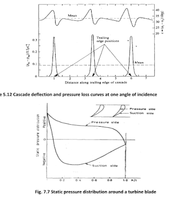
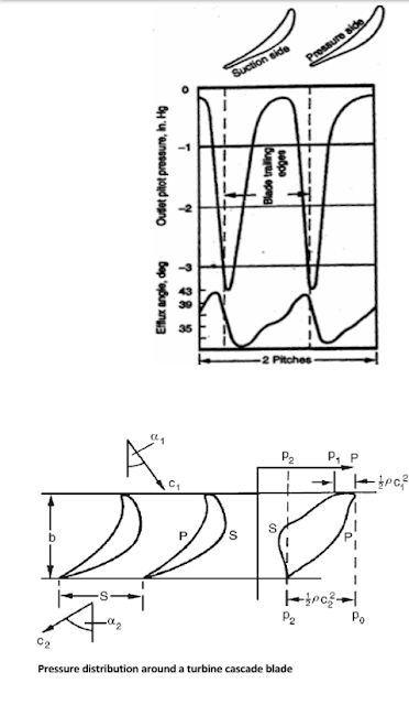
Pressure distribution around a turbine cascade blade
Turbine cascade performance
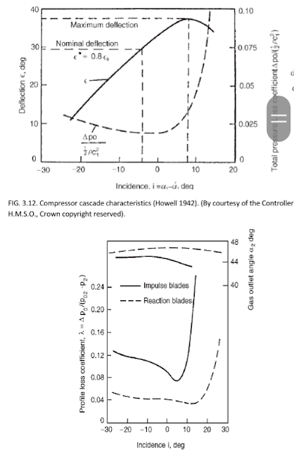
Figure 3.14 shows results
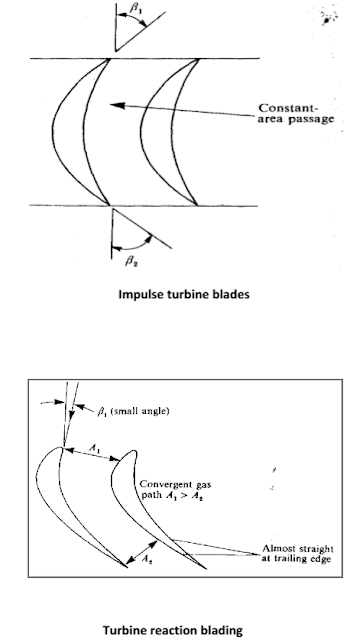
obtained by Ainley (1948) from two sets of turbine cascade blades, impulse and
“reaction”. The term “reaction” is used here to denote, in a qualitative sense,
that the fluid accelerates through the blade row and thus experiences a pressure
drop during its passage. There is no pressure change across an impulse
blade row. The performance is expressed in the form ʎ= Δpo/(po2 -p2) and ∝^2 against incidence.
From these results it is observed
that:
(a) the reaction blades have a much wider range of low loss
performance than the impulse blades, a result to be expected as the blade
boundary layers are subjected to a favorable pressure gradient,
(b) the fluid outlet angle 2
remains relatively constant over the whole range of incidence in contrast with
the compressor cascade results.
Two important geometric
variables, which define blade shape are
•
Blade thickness
distribution, t/l, and
•
Blade camber line shape
distributions y/l, which may be circular or parabolic arce form or any other
form. It determines the blade camber angle, θ.
• Blade camber and thickness distributions are generally presented as tables of y/l and t/l against x / l.
Beside the blade profile (thickness&camber distributions) there are two important geometric variables, which define the cascade are
•
the space-chord ratio,
s/l, and
•
the stagger angle,Ƹ,
The stagger angle,ξ,
is the angle between the chord line and the
reference direction (which is the tangent to or the line perpendicular to the
cascade front).
The importance of the stagger
angle, x,
It affects the following:
1- the blade angles
2- the relative amount of diffusion or
acceleration
3- the energy transfer in case of rotor
cascade (to/from the blade from/to the fluid i.e. turbine or compressor)
4- losses or drage coefficient.

Effect of stagger angle on
cascade performance.
A,B & C — compressor
cascades.
D,E & F — turbine cascades.
Turbine
reaction blading
There is a pronounced increase in
total pressure loss as the incidence rises beyond a certain value and the
cascade is stalled in this region. The precise incidence at which
stalling occurs is difficult to define and a stall point is arbitrarily
specified as the incidence at which the total pressure loss is twice the
minimum loss in total pressure. Physically, stall is characterised (at positive
incidence) by the flow separating from the suction side of the blade surfaces.
With decreasing incidence, total pressure losses again rise and a “negative
incidence” stall point can also be defined as above. The working range is
conventionally defined as the incidence range between these two limits at which
the losses are twice the minimum loss. Accurate knowledge of the extent of the
working range, obtained from two-dimensional cascade tests, is of great
importance when attempting to assess the suitability of blading for changing
conditions of operation.
A reference incidence angle
can be most conveniently defined either at the midpoint of the working range
or, less precisely, at the minimum loss condition. These two conditions do not
necessarily give the same reference incidence.
5.7 HIGH-SPEED FLOWS
Many turbines and compressors
experience flows at high Mach numbers. The high Mach number flow gives rise to
some special problems which are characteristic of only high speed flows. Most
of these problems arise due to the acceleration or deceleration (to subsonic
Mach numbers) of supersonic flows in blade passages; expansion and compression
waves are generated which affect the nature of flow and losses in these
machines.
As stated before, when the Mach
number reaches unity, the flow chokes and the maximum mass flow rate is
governed by Eq. (5.82).
It is well known that in practice
a supersonic flow decelerates to subsonic through a shock wave. This may be
either normal or inclined to the direction of flow. In actual practice both the
types of waves exist in supersonic machines.
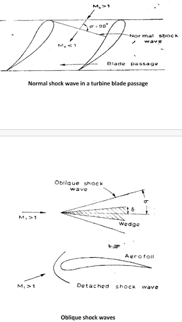
The shock wave is an
irreversibility and leads to stagnation pressure loss and increase in entropy.
HIGH-SPEED FLOWS
•
Many turbines and
compressors experience flows at high Mach numbers.
•
The high Mach number flow
gives rise to some special problems which are characteristic of only high speed
flows.
•
Most of these problems
arise due to the acceleration or deceleration (to subsonic Mach numbers) of
supersonic flows in blade passages; expansion and compression waves are
generated which affect the nature of flow and losses in these machines.
•
When the Mach number reaches
unity, the flow chokes (there is a maximum mass flow rate which is indepentent
the decrease of the downstream pressure).
HIGH-SPEED FLOWS (Continue)
•
It is well known that in
practice a supersonic flow may decelerate to subsonic through a shock wave.
•
This may be either
normal or inclined (oblique shocks) to the direction of flow. In actual
practice both the types of waves exist in supersonic machines.
•
The shock wave is an
irreversibility and leads to stagnation pressure loss and increase in entropy.
Normal
shock wave in a turbine blade passage








ليست هناك تعليقات:
اضافة تعليق